Context
At Instant-Lab, EPFL Neuchâtel (August 2024), I worked on optimising a flexure-guided angular inverter, a compliant mechanism that transmits angular motion from an input arm to an output arm while perfectly inverting its sign (θ_out = -θ_in), with minimal parasitic displacement.
Flexure-based inverters avoid friction and backlash by replacing pivots with thin elastic blades. The challenge is that blade geometry directly couples to angular error. This project derived and validated the geometry conditions for a perfect inversion.
Design Process
Analytical Dimensioning
A perfectly-inverting full-flexure mechanism requires two key conditions on blade geometry. Starting from the pivot parameters, the blade offset R and height H are determined analytically:
H / L_pivot = (2/15) · (1 / cos(α_pivot)) · (9λ² - 9λ + 1)
where λ = D_pivot / L_pivot
Applying these to the target envelope (α_pivot = 60°, L_pivot = 84 mm) gives:
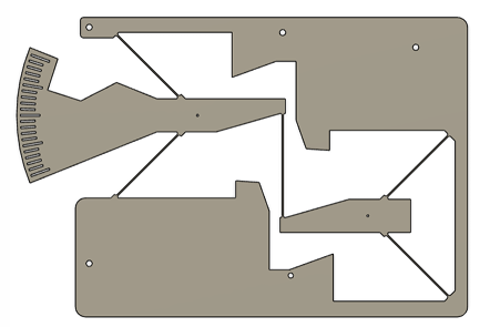
CAD Design
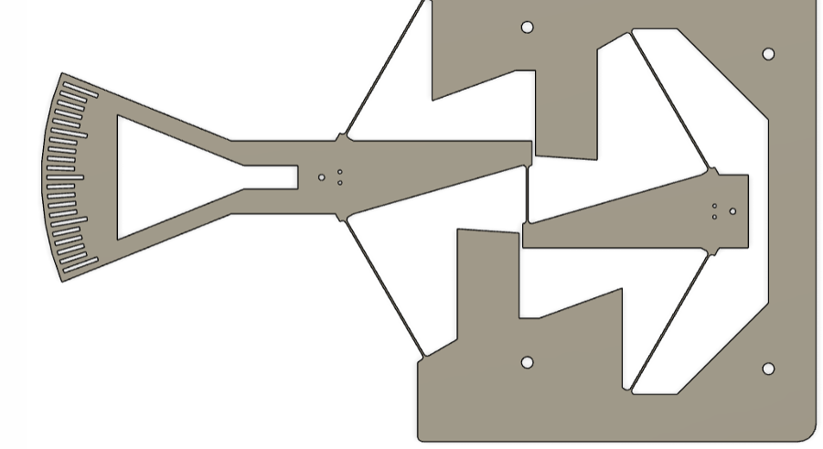
The mechanism consists of a fixed frame, two symmetric flexure stages, and a fan-shaped input arm with a protractor scale for visual angle reading. Blade geometry matches the analytically derived parameters.
COMSOL FEM Simulation
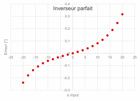
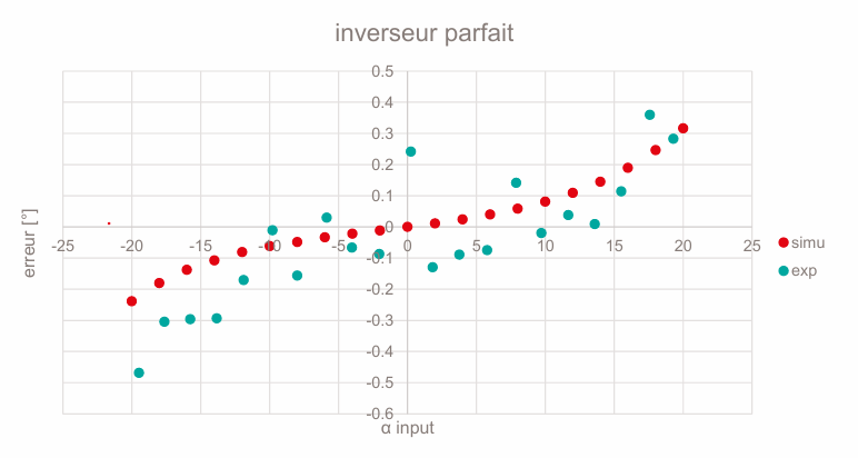
The optimised inverter was simulated in COMSOL across an input range of ±20°. Angular error (θ_out + θ_in) remained below ±0.35°, a near-perfect inversion consistent with the analytical prediction.
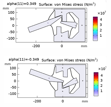
Von Mises stress maps at peak deflection confirm that stress stays well below yield, and the symmetric behaviour at +20° and -20° validates the design.
A separate simulation compared the flexure error against the theoretical ideal kinematics (four-bar linkage), showing the residual 4th-order error term Δθ ≈ -(h/2)θ⁴ characteristic of this topology.
Prototyping
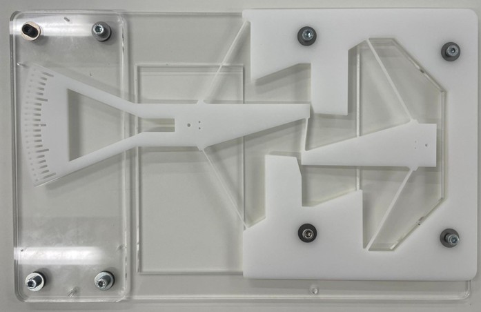
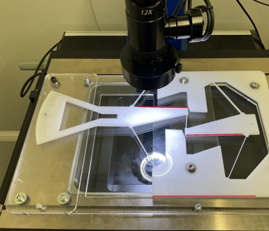
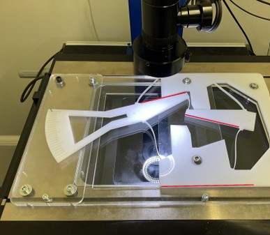
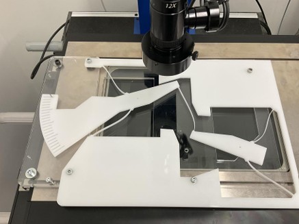
Prototypes were laser-cut from plastic sheet and assembled with bolts onto an acrylic backing plate. The fan-scale on the input arm and a reference mark on the output allow direct visual angle reading.
Experimental Validation
A 12x camera microscope measured the output angle for a series of discrete input positions. Red reference lines on the frame established a stable datum. Results were overlaid with simulation predictions.
Non-Optimised Cases
Two optimisation parameters were varied independently to quantify their effect:
- Blade offset R: setting R = 0 (blades aligned with the pivot axis) nearly doubles the maximum error
- Blade orientation: reversed orientation (rcc90, rcc120) produces a large antisymmetric error, reaching -3.5° at ±20°
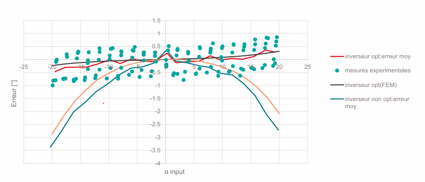
Comparison
The final comparison overlays all configurations. The optimised design (red line) stays within ±0.5° across the full measurement range, while non-optimised variants reach -3.5°. Experimental scatter on the optimised design matches the FEM prediction well.
| Configuration | Max error (FEM) | Max error (exp.) |
|---|---|---|
| Optimised (R = L/6, correct orientation) | ±0.35° | ±0.5° |
| R = 0 (no offset) | ±0.7° | n/a |
| Reversed orientation (rcc90 / rcc120) | ±3.5° | ±3.5° |