Hardware Build
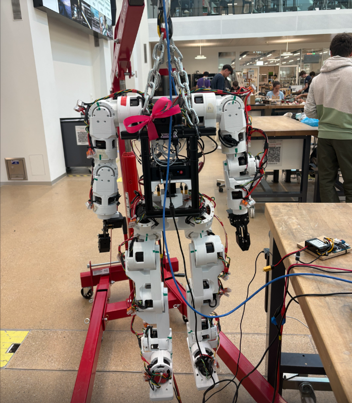
SAPIENS is built on Berkeley Humanoid Lite, an open-source biped from UC Berkeley designed for under $5,000 using 3D-printed structural parts and off-the-shelf quasi-direct-drive motors. The full robot has 22 degrees of freedom: 12 across the two legs and 10 across the two arms. As hardware lead, we handle the full build pipeline: printing and iterating all structural components, soldering and wiring the electrical systems, and performing motor calibration joint by joint.
The Task
Berkeley Humanoid Lite ships as open-source CAD files, firmware, and a parts list, not as a kit. Every structural part must be 3D-printed and iterated if necessary before assembly. The robot has 12 degrees of freedom across two legs (6 per leg), each joint driven by a brushless DC motor with a 3D-printed gearbox and a magnetic encoder. The complete build requires printing roughly 160 parts, hand-soldering all motor and encoder cables, performing electrical calibration on each of the 12 motors, and assembling the full kinematic chain from ankle to torso.
What makes this hard
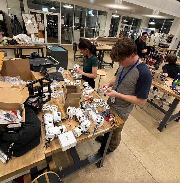
- Part count and tolerances. Around 160 printed parts must fit within tight tolerances, particularly at gear meshes and bearing seats. A part that is 0.2 mm oversized jams; undersized and it rattles. Each failure means reprinting and re-testing.
- Assembly sequence constraints. Cable routing runs inside the links, so certain bolts and connectors become inaccessible after the next link is assembled. Disassembly to fix a wiring error costs hours.
- Per-motor electrical calibration. Each BLDC motor requires measuring its flux offset, the angular gap between encoder zero and motor electrical zero, which depends on how the magnet was glued and cannot be read from a datasheet. This must be measured individually on all 12 joints.
- Gearbox alignment. The gearboxes are themselves 3D-printed. Backlash and play are sensitive to print quality and assembly alignment, and accumulate across five joints per leg.
Mechanical Assembly and Iteration
The build starts from raw filament and ends with a standing biped. Every structural part, from ankle links to the hip yoke, is FDM-printed in PETG. Iteration is central to the process: initial prints reveal fit issues at bearing seats, gear mesh contact, or cable exit points, which feed back into revised print settings or modified CAD before the next attempt.
Motor Soldering and Electrical Integration
Each of the 12 joints is driven by a brushless DC motor paired with a small controller board. The motor has 14 pole pairs, meaning its electrical angle spins 14 times faster than the mechanical shaft, so precise position sensing is non-negotiable. Every connection is hand-soldered: three phase wires from each motor to its controller, I2C lines from the AS5600 magnetic encoder, and the CAN bus daisy-chain connecting all controllers back to the onboard computer.
Motor Calibration
Field-Oriented Control (FOC) requires knowing the exact angular offset between the encoder's mechanical zero and the motor's electrical zero: the flux offset. This number depends on how the magnet was glued and the encoder mounted, so it is unique to every motor and cannot be looked up. The controller performs an automatic electrical calibration by spinning the rotor under a known current and recording the encoder response. All 12 joints are calibrated individually after final assembly.
Custom Enhancements in progress
Beyond the base BHL platform, the team is developing two hardware enhancements that extend the robot's manipulation capabilities beyond what the original design provides.
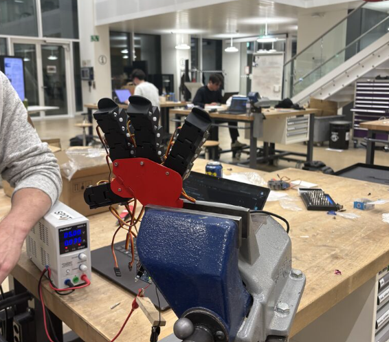
With both legs assembled, calibrated, and walking on the base BHL platform, the hardware team is now completing the dexterous hand and integration with the software stack built in parallel by the rest of the team.
Software Stack
The software stack covers the full pipeline from low-level motor control to high-level autonomy: a learned walking policy trained in simulation and deployed on the real legs, a CAN-bus arm controller with ROS2 middleware, VR teleoperation via a Meta Quest headset, and a camera-based perception pipeline for object detection and grasping. All systems run across three onboard computers coordinated over a private local network.
Locomotion: Reinforcement Learning
The walking brain is a small neural network (policy) trained entirely in simulation using Proximal Policy Optimization (PPO) via the RSL-RL library in NVIDIA Isaac Lab. Training runs 2048 parallel simulated robots on a GPU simultaneously, with each copy receiving randomized body mass, friction, and actuation gains so the resulting policy is robust rather than tuned to one exact physics model. A training run that would take months on a real robot finishes in hours on a GPU.
The policy takes 45 numbers as input at each timestep: a velocity command, body angular velocity, gravity direction in body frame, joint positions, joint velocities, and the previous action. It outputs 12 joint position targets, one per leg joint. A fast 250 Hz PD loop on the motor controllers chases these targets, while the policy itself thinks at 25 Hz. The walking gait emerges from the reward structure rather than from a gait clock: the policy discovers the left-right alternating cadence on its own because it is rewarded for keeping exactly one foot in the air at a time.
Before touching hardware, every candidate policy is validated in a second independent physics engine (MuJoCo) that it was never trained on. Policies that look good in the training simulator but fail in MuJoCo are discarded as overfit to simulation artifacts. Only policies that agree across both simulators earn a place on the real robot.
Arm Control and VR Teleoperation
The two arms each have 5 joints (shoulder pitch, roll, yaw, elbow, wrist) driven over a CAN bus at 1 Mbit/s. A single ROS2 node owns all CAN communication and translates high-level joint commands into the motor wire protocol at hundreds of frames per second. A safety watchdog inside each motor requires a heartbeat frame every second: if the host stops talking, the motor goes limp. A wall-clock-gated heartbeat in software ensures the watchdog is never starved regardless of loop rate.
Inverse kinematics maps a target hand position in 3D space to five motor angles using the Pink differential IK library on top of Pinocchio. The arms have 5 joints each, which means position (3 numbers) is always satisfied exactly while orientation is treated as a secondary goal. The IK solver runs as a QP at each tick with hard joint-range and joint-speed limits.
A Meta Quest headset teleoperates the arms in real time. The operator grips a controller to engage tracking: the target end-effector position follows the controller's translation delta while grip is held, and freezes when released. Smoothing runs as a One-Euro filter on the controller pose and a low-pass filter on the target, with a per-message slew clamp in the motor driver as a last line of defence. The full Quest-to-motor latency is approximately 15-25 ms over wired Ethernet.
Perception and Autonomy
Three cameras (a head Logitech C920 and two wrist cameras) feed a detection pipeline that identifies objects in the scene and back-projects their pixel coordinates into base-frame 3D positions the IK solver can target. Detection has two backends: a YOLOWorld open-vocabulary model that accepts any text prompt ("a red screwdriver") without retraining, and a pure-OpenCV HSV color blob finder that runs on CPU without a GPU. Once a 3D position is known, the arm can be commanded to reach it via the IK and CAN pipeline.
Camera calibration covers three layers. Intrinsics (focal length, optical center, distortion) are measured from a ChArUco board shown at roughly 15 viewing angles. An eye-on-base extrinsic places a fixed camera in the robot's coordinate frame. Hand-eye calibration for wrist cameras recovers the fixed camera-to-wrist offset so the live wrist pose from forward kinematics can be composed into a live camera pose at any arm configuration.
All software runs over ROS2 with a rosbridge WebSocket server exposing the full topic, service, and action graph to a browser-based web console. The operator can launch nodes, tune parameters, view camera feeds, and send arm goals from a single interface without touching a terminal during operation.